
![]()
HF LINEAR RF POWER AMPLIFIER
Low pass filter
Page 3 of 5
In constructing the RF coils for The Low-pass Filter Unit which is almost a band-pass because of 3 diferent trap frequency occured in each coil, I used 3/8" OD Toroids and used a Dip meter to adjust the winding of the coil appropriate to the pre- calculated/determined notch frequency and capacitance as shown in the picture. By this I got a table chart as shown below. And thanks to Microsoft Excel that simplified the calculation jobs.
Kumparan untuk LPF yang hampir berupa BPF karena adanya 3 frekwensi jebakan disetiap kumparan, saya gulung melilit toroid ukuran 3/8 inci dan mengatur jumlah lilitan dengan menggunakan Dip meter pada frekwensi jebakan dan kapasitor yang sudah dihitung/ditentukan terlebih dahulu. Dengan ini saya memperoleh daftar seperti dibawah ini.. Dan sukur berkat Microsoft Excel menjadikan pekerjaan ini lebih mudah.
| BAND | L 1 | L 2 | L 3 | C 1 | C1a | C 2 | C2a | C 3 | C3a | C4 | C4a | C 5 | C5a | C 6 | C 7 | C7a |
|---|---|---|---|---|---|---|---|---|---|---|---|---|---|---|---|---|
| All Inductance (L1,L2 and L3 ) are Toroidical coils arbitrary calculated in µH All Cap are in pF dipped mica 500 WV unless otherwise specified Relay = OMRON type 62K | ||||||||||||||||
Low Pass Frequency Band Channel Parts Table
Band 160 m = 1,6 mHz - 2.2 mHz
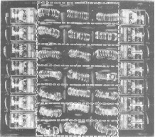
LPF Printed circuit viewed from solder side
Band 80 m = 3.0 mHz - 4.2 mHz
Band 40 m = 6.0 mHz - 8.7 mHz
Band 20 m = 12.5 mHz - 18 mHz
Band 16 m = 18 mHz - 34.5 mHz
Band 10 m = 24.5 mHz - 32 mHz
![]() LPF Printed Circuit viewed from component side
LPF Printed Circuit viewed from component side
11.5 x 13 cm