
Stacking & Transformation
(My Technical Notebook)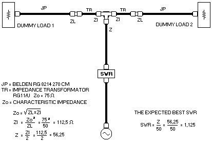
Experiment 1
Experiment 2 TR replaced with a Impedance transformation tuner
The ideal impedance transformation ratio are actualy ZL = 50 Ohm and ZI = 100 Ohm, but to get this ideal impedance transformation means that for TR, we must use a coaxial cabel with a Characteristic impedance Zo = 70.71 Ohm. There is no such coaxial cable available, unless we placed a special order to the coaxial cable maker. So what I did was using a coaxial cable with the closes Zo that is 75 Ohm RG11/U. As seen from the above calculated formula, we'll expecting a best possible SWR = 1.125.
Transformasi impedansi yang idial sesungguhnya adalah bila ZL = 50 Ohm dan ZI = 100 Ohm, namun untuk memperoleh transformasi impedansi idial ini kita membutuhkan kabel koeksial untuk TR dengan Impedansi karakteristik Zo = 70,71 Ohm. Jenis kabel ini tidak ada kecuali bila kita memesan secara khusus ke pembuatnya. Dan apa yang saya lakukan ialah mekai kabel koeks yang mempunyai karakteristi mendekati yakni RG11/U dengan Zo = 75 Ohm. Seperti terlihat dalam rumus perhitungan diatas maka kita akan peroleh SWR yang paling baik = 1,125.
First I removed the TR and connect JP straight to the T connector, with an input power of 27 Watts I got an 9 Watts equal reading at both dummy loads and SWR showed 1 : 2. Flat response within 144 ~ 148 Mhz This means that ZL= is 50 Ohm while the parallel resultant Impedance Z = 25 Ohm.
Pertama-tama JP dihubungkan langsung tanpa TR ke konektor T, dengan masukan 27 watt saya memperoleh tnjukan yang sama di kedua beban Dummy Load yakni 9 Wat sedangkan SWR menunjukkan 1 : 2. dan rata dalam daerah frekwensi 144 ~ 148 Mhz.. Ini berarti bahawa Impedansi ZL = 50 dan Hasil gabungan pararalelnya Z = 25 Ohm.
The result of the first Experiments was as follows
Hasil percobaan pertama adalah sbb,
| Frequency | VSWR Reading for TR Length of | |||
|---|---|---|---|---|
| 31 Cm | 32 Cm | 33 Cm | 34.5 Cm | |
| 144.0 mHz | 1.2 | 1.2 | 1.2 | 1.2 |
| 144.5 mHz | 1.2 | 1.2 | 1.2 | 1.2 |
| 145.0mHz | 1.2 | 1.2 | 1.2 | 1.2 |
| 145.5 mHz | 1.2 | 1.2 | 1.18 | 1.18 |
| 146.0 mHz | 1.2 | 1.18 | 1.15 | 1.15 |
| 146.5 mHz | 1.2 | 1.15 | 1.15 | 1.15 |
| 147.0 mHz | 1.18 | 1.15 | 1.12 | 1.12 |
| 147.5 mHz | 1.15 | 1.1 | 1.1 | 1.1 |
| 148.0 mHz | 1.15 | 1.1 | 1.1 | 1.1 |
Power output at both dummy load was almost equal and constant 13 Watts ea.
Daya yang keluar di kedua beban dummy load hampir selalu sama dan tetap 13 wat
The result of experiment 2 using tuning unit was
Hasil percobaan kedua menggunakan tuning unit adalah.
Almost flat for the frequency range between 144 ~ 148 mHz, power 13 watts ea and VSWR 1:1. Obviousely using impedance transformer tuning unit was more suitable, but due of the quality of the spareparts that is sensitive to weather condition influence. If used outdoors near the antenna it needs periodical retuning. It's of course inconvenient when it's place up high at the antenna mast.
Both experiments was statisfactory and the insertion lost is quite small approxiamately 1 Watt ± 0.3 dB.
Hampir rata untuk daerah frekwensi antara 144 ~ 148 mHz, daya 13 wat pada setiap beban dengan VSWR 1:1. Nyatanya memakai transformasi ini lebih cocok namun, karena mutu suku cadang yan mudah terpengaruh oleh keadaan cuaca memerlukan peneraan ulang bila dipasang diatas antenna. Hal ini tentuk tidak mudah bila diletakkan tinggi diatas tiang antena.
Kedua percobaan memuaskan kerugian daya hanya sekitar 1 Wat ± 0.3 dB.
Updated February 2000.-