3 x 3/4 l 2 meter Vertical antenna
My Technical Notebook
I made this 2 meter homebrew antenna in May 1982, previously I used a 5/8 l for local communication. Obviously at that period there are too many 2-meter operators using high power transmitter and factory made antenna. I was using a 10 Watt FT221 2 meter and Asahi 5/8 vertical antena factory claimed gain ± 3.8 dB. Some times my QSO partner could not read my signal even I used the optimum power that can be delivered from my FT221. Apparently my partner was suffering from cross-modulation remedies. Well then after considering between adding a RF power amplifier or improving the antenna performance, I decided to enhanced my antenna gain rather than wasting power that will just made the frequency more crowded with cross-mod. I start choosing which kind of antenna. Because the purpose was for omni-direction radiation so it must a vertical collinear one. After I made several calculations and the radiating angel I choose the 3 x ¾ Theorytical I may have a gain between 6 to 9 dB.
Why did I choose a non rigid antenna construction?
I considered the Ideal Ø to l ratio of the radiating elements, for optimum antenna performance
It was rather hard in using the same metal materials for different parts of the antenna. And moreover I don't have metallurgy knowledge for choosing the right materials in order to avoid using two opposing chemical characters (known as + and -) Combining opposing metal character might caused an anodizing layer effect occurred in between the junction. If this happened than the junction will act like a diode and for sure I got noise and cross-mod troubles caused by the symptom. May be I am a paranoid and overdo it but one of my technician at my office got bad experience from this symptom when he erect a factory made H.F. logperiodic antenna. Noises occurred when it was raining even small drizzling and disappeared in clear and shiny conditions.
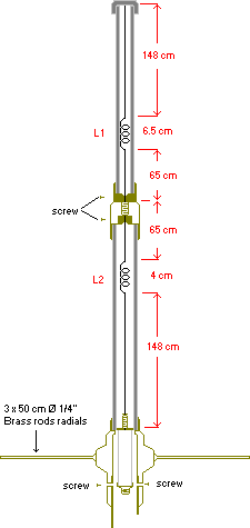
The antenna has 3 radiating elements. The phasor coil L1 and L2 functioned as phase shifters in order to maintain equal phase in all 3 radiating elements.
![]()
![]()
![]()
![]()
![]()
![]()
![]()
Description

The TOP unit is made of one piece copper wire Ø 2.5 mm OD the first upper section is formed straight 148 cm long after that the middle section is wound 9 turn to form a coil of Ø 9mm ID length of 6,5 cm, the lower section is formed straight again for a length of 65 cm.
This unit is inserted into a PVC plumbing tube Ø ¾", the top is covered with a PVC cap while the lower side is screwed (embedded) and glue into a brass connector the lower part of it is fastened into it with a srew. And adjusted to maintain the total length of the upper section unit included the brass connector remain 219.5 cm.
The lower unit is made of one piece copper wire Ø 2.5mm and is physical inverted to the upper unit the only difference is the phasor coil L2 11 turn Ø 12 mm ID length 4 cm and Total length 217 cm.
is place in PVC Tube of Ø 1¼" attached on the upper side is a brass connector the topside of the lower unit is fastened to it by a screw. While the base part is inserted and screw to the matching unit inside the brass base unit.
I used 3 pcs of brass rods radials Ø ¼" attached to the base unit. In adjusting the antenna performance, I found out that the angle of radiation will be much improved when the radials is bend downwards ± 120°. A galvanised waterpipe is attached to the brass base unit which perform as a bracket extension to hold the antenna onto a mast or booms using U bolts.
In attaching the PVC tubing with its ends that is made of brass I used Power Glue.
Unit atas dibuat dari kawat tembaga diluruskan sepanjang 148 cm kemudian diteruskan dengan melilit bagian tengah menjadi kumparan 9 lilit pada Ø dlm 9mm dan panjang kumparan 6,5 cm lalu dlanjutkan secara lurus sepanjang 65 cm. Panjang keselurhan bagian atas adalah 219,5 cm.
Unit ini dimasukan kedalam pipa Pralon ukuran ¾ inci yang bagian atasnya ditutup dengan dop pralon sedangkan bagian bawah di sekrup ke sebuah tutup terbuat dari kuningan, bagian bawah unit atas antenna di solder ke tutup kuningan ini dan panjang keseluruhannya berikut tutup ini diatur supaya tetap 219,5 cm
Unit bagian bawah dibentuk dengan bahan kawat tembaga yang sama seperti bagian atas dan merupakan bentuk bangun kebalikan dari bagian atas, perbedaannya hanya pada kumparan penyesuai fasa L2 11 lilit Ø dlm 12 mm panjang kump 4 cm. Unit ini ditempatkan dalam pipa pralon Ø luar 1*frac14; inci dengan pajang 217 cm. Ujung bawahnya di sekrup pada unit matching yang ditempatkan didalam unit dasar antena yang terbuat dari bahan kuningan. 3 batang jari-jari dari bahan kuningan Ø ¼ inci dilekatkan dibagian dasar, dan dari penyetelan ternyata sudut pancaran antena akan lebih baik bila ditekuk kebawah ± 120°. Pegangan antena berupa pipa ledeng tersambung langsung di unit dasar dan dipasang ketiang antenna mengunakan baut U.
Dalam menyambung pipa pralon kebagian ujungnya yang terbuat dari kuningan, dipakai lem Power Glue.Dipasaran saat ini terdapat pipa pralon yg lembek sehingga bila didirikan secara vertikal akan melengkung, jika ini menjadi kendala maka, sebaiknya untuk membuat kekakuan pipa di lapisi dulu dengan resin fiberglass.
Matching unit
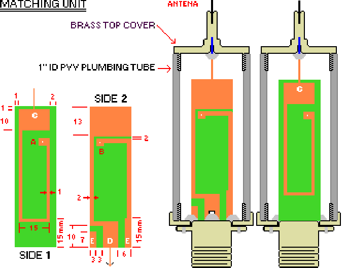
Matching unit is made from a 18 x 70 mm. double side Epoxy PCB. Point A on side 1 is joined together with point b on side 2. Point C on side 1 connected to upper brass cover of the matching unit where the lower section antenna unit is firmly screwed. While point D and E on side 1 was firmly soldered to the inner and ground conductor of a female coax connector located at the bottom side of the matching unit. The matching unit is placed in a PVC tube with a suitable length .

To zoom please click at the image.
TEST RESULT
| V.S.W.R. TEST | |||
|---|---|---|---|
| FREQUENCY | VSWR | ||
|
144.0 mHz 144.5 mHz 145.0 mHz 145.5 mHz 146.0 mHz 146.5 mHz 147.5 mHz 148.0 mHz |
1 : 1.5 1 : 1.4 1 : 1.25 1 : 1.2 1 : 1.15 1 : 1.25 1 : 1.35 1 : 1.45 |
The VSWR test result as shown in the table next to this was done ± 3 m elevated above the ground level. I got a better VSWR (1 : 1 at 146 mHz) after I installed it to an antenna mast of about 10 m high and test it alternately with my old 5/8 antenna to find out the differences. Checked with my friend who is about 17 km away from my QTH. I Observed the receiving signal was remarkable improved and the reports from my friend were either good. He told me that my signal was 3 dB stronger compared with the old 5/8 antenna. | |
Updated February 1999