A Complete FM Radio on a Chip AN192
AN192
Page 7 of 11
Filter and demodulator capacitors. The values shown
are for an i.f. of 70kHz. For other intermediate
frequencies, the values of these capacitors must be
changed in inverse proportion to the i.f. change.
C14:
Decouples the reverse r.f. input. It must be connected to the common return via a good quality short connection to ensure a low-impedance path, Inductive or capacitive coupling between C14 and the local-oscillator circuit or i.f. output components must be avoided.
C15
Decouples the d.c. feedback for if. limiter/amplifier LA1
Cl 9 and C21:
Local-oscillator tuning capacitors. Their values depend on the required tuning range arid on the value of tuning capacitor C20.
C22, C23, L l, L2:
The values given ate for an r.f. bandpass filter with Q = 4 for the European. and U.S.A. domestic f.m. broadcast band (87.5 MHz to 108 MHz). For reception of the Japanese f.m. broadcast band (76 MHz to 91 MHz), Ll must be increased to 78 nH arid L2 must be increased to 150 nH. If stopband attenuation for high level a.m. or tv signals is not required, L2 and C22 can be ornitted and C23 changed to 220 pF.
R2:
The load for the audio output current source. It determines the audio output level, but its value must not exceed 22 kohm for Vp = 4.5 V, or 47 kohm for Vp = 9 V
|
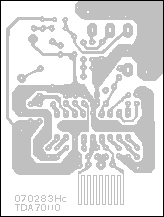
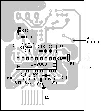
Fig.12 Exprimental printed wiring board for the circuit of Fig.1


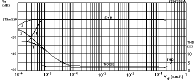
Fig.13 Audio output as a function of input e.m.f. The curves numbefed 1 were messured with the
muting System active. The curves numbered 7 were rrmasured with the muting system disablod by
injecting about 20yA into pin 1 of the TDA7WO. The input frequency was 96MHz modulated with
1 kHz with a devistion of ± 22.5 kHz for theSutput level curves,and ±75 kHzforthadisto"ion curve

