<=20A=
<=21=
<=22=
<=23=
<=24=
<=25=
R152, 2500-Ohm, variable resistor was 1000-ohm variable resistor. This change allows a greater range ot receiver If gain adjustment. If replacing this eomponent, recommend replacing with 2500-ohm variable resistor.
R200, 1 megohm, added. This change back-biases second transmitter mixer to cutoff during receive. If this component is not in the unit, it does not have to be added.
Rl43, 2200 ohms, was 1500 ohms. This change improves decoupling. If replacing this com ponent, recommend replacing with 2200 ohms.
C69, 240 pF, was 220 pF. This change provides greater crystal oscillator plate tuning rang for 3.6 band. If replacing this component, reeommend replacing with 240 pF.
C274, 0.01 µF and L40, 220 ohms, added. These changes improve decoupling. lf these components are not in the unit, they do not have to be added.
R82, 4700 ohms, 1/2 watt, was 4700 ohms, 1/4 watt. This change gives longer resistor life at existing power dissipation level. If replacing this component, recommend replacing with 1/2-watt resistor.
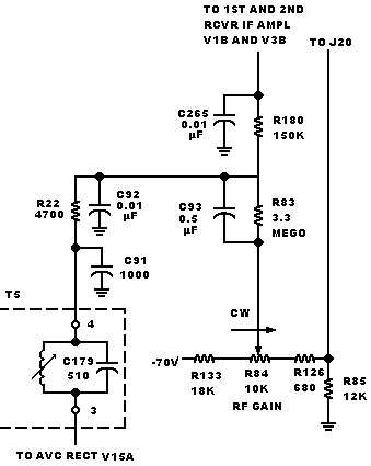
Some early units have an AVC time constant circuit as shown below. This circuit has been changed to the configuration shown on the schematic to eliminate AVC overshoot on noise pulses and lo provide dual time-constant action. If repairing the circuit shown below, recomdend that existing configuration be malntained. Reference part A of service bulletin no 8.

Changes made to the circuit above to produee the circuit shown on the sehematic are as follows: C265, 0.01 µF and connected in parallel with R80,was 0.001 µF and connected between the AVC side of R180 and ground; C93, 0.47 µF, was 0.05 µF; R180, 680 kW, was 150 kW; R8:1,.5 megohms, was 3.3 megohms; and R82-C92 were disconnected from junction of R180-R83 and reconnected to AVC side of R180.
KWM-2 and KWM-2,A Transceivers. Schematic Diagram
figure 7-l (Sheet A)