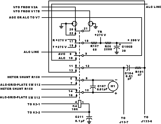
R211, 470 ohms, added and IllD0, 1500 ohms, was 2200 ohms. These changes shift the ALC line bias to reduce transmit gain variations between LSB, USB, and CW positions versus TUNE and LOCK positions of the EMISSION control. If repairing this circuit, recommend that same configuration be maintained.
Restated all notes.
C155, 63- to 320 pF variable capacitor, was 15- to 120-pF variable capacitor. This change improves pa output loading on 15- and 10-meter bands. If replacing this component, recommend replacing with 63- to 320-pF variable capacitor.
R215, 47 ohms, is added in series with the screen grid of tone oscillator V2D to act as a parasitic suppressor.
KWM-2 and KWM-2,A Transceivers. Schematic Diagram
figure 7-l (Sheet A)