R209, 100 ohms, added. This change improves isolation betwecn af output and the antiVOX circuits. If this component is not in the unit, It does not have to be added.
R182, 47 ohms, was 68 ohms, This change was made to prevent at output amplifier from oscillating, effective CI 72196. When replacing R182, recommend replacing with 47-ohm resis tor.
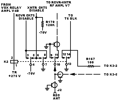
K2 and K4, enclosed type, were open-telephone type relays. The circuits for the enclosed type are shown on the schematic. The open-telephone relay circuits are shown below tor K2 and on the following page for K4. This change reduces relay failure in severe environment. The two types of relays are not interchangeable. If repairing relay K2 or K4 circuits, check the relay type; and if old relays are used, install service bulletin no 7 (reissue).
Schematic corrections; R170, 100 kW, was R70, 100 kW; V8-3 was V8-8; and V8-8 was V8-3.
Ungrounded receive antenna shield at K2-9. This change eliminates oscillations on the receive antenna line when the KWM-2/2A is operated around 28 MHz. If your unit is operated around the above frequency and you encounter the oscillations, unground the shield at the K2-9 end of the receive antenna line. If this problem does not pertain to your unit, do not make the change.
C227, 0.01 µF, was added. This change provides a high-frequency bypass and eliminates ultrasonic oscillations that cause increased noise and audio distortion. If this component is not in your unit, It is recommended that you add it.
Refer to above for a description of the change in K4 relay from open telephone (shown on page) to enclosed (shown on the schematic).
KWM-2 and KWM-2,A Transceivers. Schematic Diagram
figure 7-l (Sheet A)