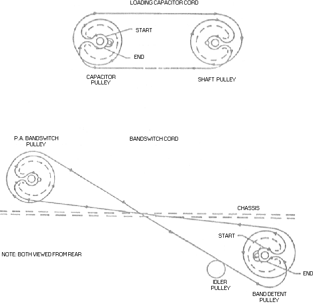
 Dial Cord Stringing Diagram
Figure 4-4
to state the desired length in feet. String the cord according to the band-switch cord illustration in figrure 4-4. Make sure cords do not overlap on the pulleys. Pull cord tight and tie to the tab. Mash the tab down to clamp the cord securely. Tighten the idler gear to bring the cord to tension.
Turn the band switch to position 3E and check to see that the movable contact (rotor blade) of both S7 and S8 (refer to figure 6-1for location ot S7 and S8) are at positions 1 and 2. This may be delermined by counting clockwise on the wafer from the X-mark. The X-mark should be visible on the left side ot S8 (as viewed from the fronT of the KWM-2/2A) without the pa cage removed. If the movable contacts are incorrectly positioned loosen the pa band-switch pulley and turn the switch to its proper position. Tighten the pa band-switch pulley.
Apply a little airplane cement on the dial cord knots to keep them tight. After the cemEnt is dry trim the loose End back NO CLOSER than one-quarter inch from thE knot.
Remove the power cable from the KWM= 2/2A.
Remove the pa cage by unscrewing the five self-trapping Phillips-head screws (located on the bottom side of the chassis) that secure the cage to the chassis.
Using a knife or small screwdriver. pry open the tabs and remove the hroken o defective cord from the two loading capacitor pulleys.
Manually position the loading capacitor to its fully meshed position and the INCR LOAD control to position 10 on the P A TUNING logging scale.
Stringt the cord according to the loading capacitor cord illustration in figure 4 Makc sure cords do not overlap on the pulleys. Pull cord tight and tie to the tab. Mash the tab down to clamp the cord securely. Tighten the idler gear to bring the cord to tension. Check to make sure that the loading capacitor and INCR LOAD control are still in the positions set up in