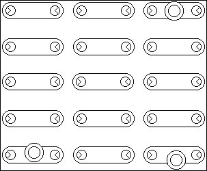
 Crystal Socket Location:
Figure 2-3
if the desired band is 4.0 to 4.2 MHz 4.0 MHz plus 3.115 MHz equals 7.155 MHz. b. If lower edge of desired 200-kHz band is 12.00 MHz or higher the required crystal frequency is half the sum of the lower edge of desired band plus 3.155 MHz. As an example if the desired band is 14.4 to 14.6 MHz:
(14.4+3.155)/2 = 8 7775 MHz.
The plate circuit of the oscillator is tuned to twice the crystal frequency when required injection frequencies are this high.
Avoid transmitter operation between 5.0 and 6.6 MHz. In this range the second harmonic of the vfo and the variable if frequency is nearly the same as the desired frequency. In transmit function some of this energy will pass through the tuned circuits and become spurious emission.
e. Plug substitute or extra crystals into the appropriate socket on the mounting board according to Band-switch position and crystal frequency columns in table 2-3. The
example cited in step b above calls placement of the crystal in one of the sockets marked C. If two additional 10-mHz crystals are used they must be Plugged in the sockets marked E. Table 2-3 lists crystal socket designations. switch positions (BAND), and crystal frequencies furnished.
The KWM-2A is equipped with an extra crystal mounting board and a front-panel switch to allow selection of either board The crystal mounting board for extra-band operation is located on the top of the chassis. If amateur band operation is not needed extra-band crystals may be substituted in the crystal mounting board under the chassis. Be sure the crystals are plugged into appropriate sockets according to information of table 2-3 and figure 2-3. The transmitter can be operated at other frequencies outside the specified amateur band or at other 10-meter frequencies by plugging the proper crystals into the mounting boards
Mark the desired lower band edge information on the white card in the band-switch windows. Make sure this information is marked in the appropriate switch position
2..5.2 Adjustment of Tuned Circuits
For operation outside amateur bands disregard amateur band markings on EXCITER TUNING and P.A. TUNING scales and use logging scales. Figure 2-2 shows logging scale calibration curves. Operation at frequencies outside the amateur bands will result in slightly decreased receiver sensitivity and transmitter pa grid drive unless the tuned circuits of the transceiver are retuned to peak their responses in the desired portions of the high-frequency spectrum. For moderate excursions from the amateur Bands the decrease in performance is minor and realignment of the rf circuits is usually not necessary unless optimum performance is desired. Adjustment of the trimmer capacitors only will normally be sufficient to peak the response outside the amateur bands. Figure 4-1 shows the location of these adjustments. The letter portions of the capacitor designations correspond to the frequency