Mounted at the bottom front of the housing is stop arm assembly 260. The right (from front of chassis) end of the arm ends in a hook. The left end has a roller that is held firmly against the outer edge of the dial by a spring. A portion of the outer edge of the dial is cut away so that as the ends of the dial scales are reached, and as the roller on the stop arm follows the dial, the hook on the other end of the dial drops and engages the rotating stop 263 mounted on the tuning shaft in front of the pinion gear. This action provides a positive stop at the ends of the tuning ranges on all bands. The tuning shaft is geared to the tuning capacitor through worm gear 265, small split gear 267, pinion gear and bushing assembly 268 and the split gear on the tuning capacitor shaft. Pinion gear and bushing assembly 268 is fastened to the cross shaft by means of two set screws. When these screws are loosened, the tuning capacitor is disengaged from the dial and mask assembly, and the relationship between the dial and the tuning capacitor may be adjusted. Altached near the top of the housing is guide arm assembly 271, which, with the spring 274, positions detent wheel 273. The detent wheel is the six-pointed wheel mounted near the end of the band switch shaft and serves to position the band switches. The slotted coupling on the end of the band switch shaft couples |
the band switch shaft to bracket and gear assembly 277. 32. SERVIClNlG THE DIAL AND MASK ASSEMBLY. a. REMOVAL.—Before the dial and mask assembly may be removed for scrvicing, the front panel must be removed as directed in Paragraph 30a. When this has been done, the dial and mask assembly is held in place by only two hex head mounting screws found on the underside of the chassis. One of these screws is under the i-f shield plate 251, (see Figure 18) and is accessible only after this plate is removed. After the two mounting screws are removed, the assembly may be lifted from the chassis and serviced. b. DISASSEMBLY.—To remove dial mask 256, dial 257, dial index plate 258, or the band switch shaft, the taper pin fastening the hub of the mask to the shaft must be removed. While this is being done, be certain to support the shaft so excess strain will not be placed on the center bushing and shaft. After the taper pin has been driven out, the parts may be readily removed. c. DIAL REPLACENIENT.—Before replacing the dial, be certain that spring washer 289 between the dial hub and the housing is mounted with its convex side towards the dial hub. The dial is slipped on over the center bushing and the teeth in the dial gear engaged with the teeth of the |
|
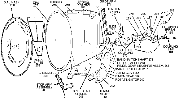
Figure 9 Radio Receiver BC-348-J, Dial and Mask Assembly