on the front panel will vary the frequency of the c-w oscillator approximately 4,000 cycles each side of the zero beat position (Arrow on knob pointing up.) The effect of ambient temperature variations are minimized by the use of a temperature compensated tuned circuit. lThe c-w oscillator operates at an extremely low level minimizing harmonics and stray oscillator pickup. The output is capacitively coupled to the plate circuit of lhe second amplifier tube by a twisted wire capacitor. Amplification by the third i f amplifier stage the gain of which is not controlled either manually or by a-v-c provides sufficient output from the c-w oscillator to the diode detector. This value of oscillator output is somewhat below the level at which the a-v-c operates, thus permitting the use of automatic volume control even for c. v reception. b. C-W oscillator switch 168 in the ON position suplies the oscillator plate voltage and increases the a-v-c time constant by connecting the additional capacitor 64. |
Switch 168 supplies the oscillator plate voltage by connecting to the screen grids of the first and second i-f tubes. The same switching shunts resistor 10l-2 across plate resistor 101-l, which drops the gain in the first i f tube to a value that reduces the sensitivity by an amount sufficient to keep the overall set noise essentially constant. 24. CRYSTAL BAND-PASS FILTER.Additional selectivity is available by the use of the i-f crystal filter follov.ing the first i-f amplifier rube. Of interest in connection which this filter is the bridge circuit composed of auto transformer 150, a neutralizing capacitor and the capacity of the crystal holder. See Figure 5. Undesired signals transmitted through the capacity of the crystal holder to the grid of the second i-f tube are neutralized by an opposite voltage developed in the auto transformer, and made equal to the undesired grid voltage by the neutralizing capacitor. |
|
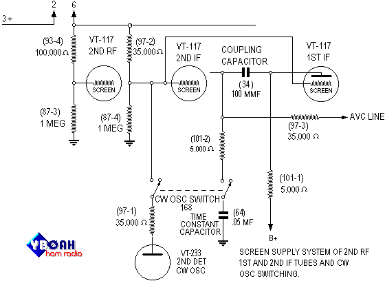
Figure 3-C.W. Oscillator Switching