SECTION III
Principles of Operation
|
| Page 3 - 2 |
|---|

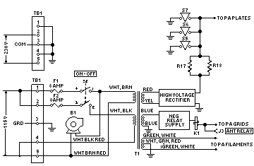
Fig 3 - 2. Control and Interlock Circuits
attack, slow-release characteristic. The alc threshold is controlled by the amount of reverse bias on CR19. This voltage is developed across R7 in the plate supply bleeder network, an varied by potentiometer R16. It is adjusted at the factory for optimum operation in conjunction with the internal alc circuits of exciters such as the KWM-1, KWM-2/2A, or 32S-1. Normally it will not need readjustment.
This system allows a high average level of modulation and optimum power output from the amplifier, within the rated limits of distortion.
METERING CIRCUITS.
One section of the METER switch, S3. selects the output voltage from a tuning and loading bridge circuits.
This circuit consists of the power amplifier tubes, CR17, CR18, and the associated load resistors and filter networks. The bridge is balanced when the plate circuit TUNING and LOADING controls are adjusted to present the proper load impedance to the power amplifier plates. The meter then will read zero.
The second section of the meter switch connects the meter to the plate supply through a four-megohm multiplier resistor to indicate the d-c voltage output. It is read on the D.C. KILOVOLT scale.
The third section of the meter switch connects the meter, through R10, across shunt, R8. This indicates power amplifier plate current. It is read on D.C. AMPS scale.
|
| Page 3 - 2 |
|---|