
![]()
MOBILE
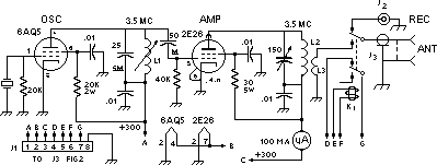
Fig.1 -- Circuit of the r.f. section of the ash-tray 80 meter transmitter.
L1 - 40 turns No. 28 enam. on CTC LS-4 iron slug form.
½-inch diam.(approx. 35 µh.).
L2 - 30 turns No. 20 enam, 1 - inch diam.
L3 - 1 turn No. 20 enam, wound over end of L 1
(Scotch Electrical Tape between windings).
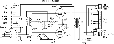
Fig. 2 -- Circuit of the modulator for ash-tray mobile rig. showing power and control cable connections.
J2 - 3-terminal microphone connector.
J6 - Female octal connector.
J6 - 2 - terminal male connector.
K-007X or equivalent).
T2 - Modulation transformer, 10,000 to 8000
ohms (Perrless M-013X or equivalent).
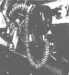
The ash-tray mobile rig installed in the instrument panel of W7KOT's station wagon.
Also brought out to the panel by means of an extension shaft. The panel affords space for 1½-inch milliammeter which is not only indispensable in tuning the transmittee; but also adds to the appearance of the unit. A change-over relay is included which shifts the antenna between transmitter an receiver, and also turns the receiver B supply off while transmitting. The Panel is made of sheet brass or aluminiu,. It is cut and bent to fit the ash-receiver opening and contour of the dash. A framework, also of aluminium strip, provides a mounting for the tubes and other components.
The modulator, whose circuit is shown in in fig. 2, is built as a separate unit on a 4X6X2 - inch chassis tucked up out of sight under the dash. The 1955 Chevrolet has a 12 - volt electrical system. For this reason, 6AQ5s were selected for the modulator, since their 600 - ma. heaters are more suitable for series connection.1 The paral-
1 This results in somewhat high voltages for both groups of tubes. It would be safer to connect a 1.5- ohm resistor in series with the battery - Ed.