Interesting Projects as seen from other Sites
Taken From JF10ZL Homepage
Self Powered Wireless Microphone

tank coil circuit 10 : 6 turns on FCZ5 Ø10 mm
This is AM transmitter, using no power supply. It moves only by the voice power. Audio power is translated for electric power and it excite radio frequency oscillator. And by the way, audio power modulates the radio frequency signal. 8cm speaker is used for the microphone. The audio signal is rectified by the diode (D1). C1 capacitor is charged for 2 volts by the big voice. Small voice add the modulation signal upon the DC voltage. You must speak like "Waaaaaaaaaa this is jf1ozl Waaaaaaaaa cqcq". This transmitter generate about 20 micro watts radio frequency energy. You can use it only the same room, between this transmitter and the radio.
Note:
All the drawings in this page was prepared by me except the relating description was originally copied as it is.
SWEEP GENERATOR


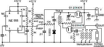
Fig.1 Circuit diagram ![]() Fig. 2. R1,2,3 = 300 ohms FL=filter under test
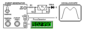
Fig. 2. R1,2,3 = 300 ohms FL=filter under test
Hand made sweep generator made to adjust the pass band of crystal filter I made the sweep generator. I can adjust the band pass character of the crystal filter easy with it. Fig 1 is circuit of this generator. Fig 2 indicates how to use it. See fig 1! Saw shaped signal(vvvvvvvvv) is made by IC555. This signal is 0.1Hz. When the SW1 is turned to sweep, the voltage of varicap(=1S553) is changed. Therefore the frequency of the oscillation by Q1(2sk439) changes for 10kHz by 0.1Hz. Q2 is impedance changer. And the oscillation frequency is changed by 60pf varicon from 7MHz to 11MHz. See fig2. One of output of this machine is connected to the counter. Horizontal arc of the X-Y oscilloscope is connected to Y-output of this machine. Another output of this machine is connected to the crystal filter.
And the output of filter is connected to X-arc of the oscilloscope,after detector(=1N60). At first tune the sweep frequency by 60pf! Then you can get the shape of the filter ,indicated as the figure. Secondly, turn the switch to the manual side! And turn the manual control dial(=5Kohm,VR)! Then the point of light changes it's position on the scope. Then you can read the counter. you can know the band pass character of the crystal filter. If the pass band of the filter is wider than your hope, change the capacitor of the filter bigger. See fig 3! And if the pass band of the filter is narrower than your hope, change the capacitor of the filter smaller. Unless this system, you need 6 hours to adjust the filter. But with this system you can do it only with 30 minutes.
YBØAH Comments
I have tried this JF10LZ sweep generator and found out that its really very handy for designing Homebrews lattice xtal Filters. In order to know the exact frequency along the curve, the RF output of the Sweep generator may be mixed with another frequency generator (I used a Precision one). By doing this I can see marks along the curves when the applied precision generator freq. is within the range. This idea was adopted from the marking techniques of TV Sweep & Marker Generator.