
|
|
|
HF LINEAR RF POWER AMPLIFIERSCEMATIC DIAGRAMPage 2 of 5Circuit description 100 Watt RF Linear Power amplifier
| |
Transistor 2SC1589 received driving RF signal from the transceiver. The amplified RF output is then fed to the driver stage 2 x 2SC2395 proceeded to The final stage 2 x 2SC2290. Both Driver and Final stages are push-pull; class AB linear configured using RF negative feedback to suppressed the 3rd order IMD. The 1N4002 diodes provide proper operating bias of 2SC2395, the stabilized voltage of 1708 an 2SD235 voltage regulator section is applied to the CT secondary winding of T2 provides bias voltage for the 2SC2290 final transistor, and adjusted for a total collector idling current of approximately 200 mA.
| 
|
Transistor 2SC1589 memperoleh dorongan RF dari tranceiver. Hasil penguatannya kemudian diteruskan ketingkat driver terdiri atas 2 x 2SC2395 untuk diumpan ke bagian akhir 2x 2SC2290. Kduanya dihubungan secara balance, kelas AB dan menggunakan umpan balik RF negatip untuk menekan IMD urutan ke 3. Dioda 1N4002 menentukan tegangan panjar yg tepat untuk 2SC2395, dan tegangan dari rangkaian penetap tegangan 1708 berikut 2SD235 disalurkan ke CT gulungan sekunder T2 untuk tegangan panjar dari 2SC2290, dan diatur agar jumlah arus kolektor adalah kira-kira 200 mA. 
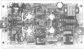
Power Unit Printed circuit Board | |